Graeme Winter
ADC Behaviour
Want to average across 5 x time points (say) from ADC to improve the time resolution / remove artefacts from ADC reading code from couple days back. Since read time is 2µs we have 250 instruction cycles to do that -> should be fine for RT system, just need to actually implement. Hardware divider takes 8 cycles so that will be fine too.
But before, wanted to confirm how ADC actually works. SARADC copies voltage before the search for a bit pattern to match -> verify by code, drive a hard signal which would show the variation if there was some to see.
Test
PIO -> 4µs square wave (250 kHz):
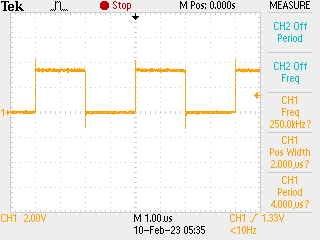
Generated and read back by following code: N.B. there are no assumptions about things being in phase, and 0.4% chance that this is the case (ran multiple times, p(in phase) ~ 0) -
from uctypes import addressof
from machine import mem32, Pin
from array import array
import math
import rp2

# output pin - connect to ADC0 by jumper
p0 = Pin(0)

# counter program using side-set to control output: counts
# for two more ticks than the content of the osr says (because
# mov and the structure of jmp)
@rp2.asm_pio(sideset_init=rp2.PIO.OUT_LOW)
def square():
    wrap_target()
    mov(x, osr).side(1)
    label("high")
    jmp(x_dec, "high")
    mov(x, osr).side(0)
    label("low")
    jmp(x_dec, "low")
    wrap()


sm = rp2.StateMachine(0, square, sideset_base=p0)

# want 4µs cycle -> 250 ticks high / low -> should see phase
# clearly as not saturated values if run. also clocks the value
# into ISR to avoid instruction in loop above
sm.put(250 - 2)
sm.exec("pull()")

# configure the scratch buffer - 200 elements of uint16_t
COUNT = 200
scratch = array("H", [0xFFFF for j in range(COUNT)])
address = addressof(scratch)

# ADC and DMA set up by means of register access (could do this with machine.ADC)
# zero-out the pin (set the function to NULL, needed for ADC)
IO_BANK_BASE = 0x40014000
GPIO26_CTRL = IO_BANK_BASE + 0xD4
mem32[GPIO26_CTRL] = 0b11111

# ADC inc. FIFO - registers
ADC_BASE = 0x4004C000
ADC_CS = ADC_BASE + 0x0
ADC_RESULT = ADC_BASE + 0x4
ADC_FCS = ADC_BASE + 0x8
ADC_FIFO = ADC_BASE + 0xC
ADC_DIV = ADC_BASE + 0x10

# DMA registers
DMA_BASE = 0x50000000
CH0_READ_ADDR = DMA_BASE + 0x0
CH0_WRITE_ADDR = DMA_BASE + 0x4
CH0_TRANS_COUNT = DMA_BASE + 0x8
CH0_CTRL_TRIG = DMA_BASE + 0xC

# control register: see table 124 in data sheet - follow ADC DREQ,
# increment write pointer, data size 2 bytes (N.B. will be 12 bit
# not 16 like usual ADC with read_u16())
#
# DREQ 36 / 0x24 for ADC for CTRL.DREQ_SEL
QUIET = 0x1 << 21
DREQ_ADC = 0x24 << 15
WRITE_INCR = 0x1 << 5
DATA_SIZE = 0x1 << 2
ENABLE = 0x1

mem32[CH0_READ_ADDR] = ADC_FIFO
mem32[CH0_WRITE_ADDR] = address
mem32[CH0_TRANS_COUNT] = COUNT
mem32[CH0_CTRL_TRIG] = QUIET + DREQ_ADC + WRITE_INCR + DATA_SIZE + ENABLE

# drain FIFO before we start
while (mem32[ADC_FCS] >> 16) & 0xF:
    _ = mem32[ADC_FIFO]

# ADC_FIFO configuration - set threshold, clear, enable DREQ and enable FIFO
THRESH = 0x1 << 24
CLEAR = (0x1 << 11) + (0x1 << 10)
DREQ_EN = 0x1 << 3
FIFO_EN = 0x1
mem32[ADC_FCS] = THRESH + CLEAR + DREQ_EN + FIFO_EN

# start the clock
sm.active(1)

# ADC configuration - since using channel 0 only just enable and start many
# then wait for the DMA to complete as an indication that we have all our
# measurements
BUSY = 0x1 << 24
mem32[ADC_CS] = 0x8 + 0x1

while mem32[CH0_CTRL_TRIG] & BUSY:
    continue

# disable ADC
mem32[ADC_CS] = 0

# stop the clock
sm.active(0)

# show results
for j, s in enumerate(scratch):
    print(j, s)

p0.off()
Results
Indeed the SARADC works as advertised - results come back effectively as 0x0 or 0xfff:
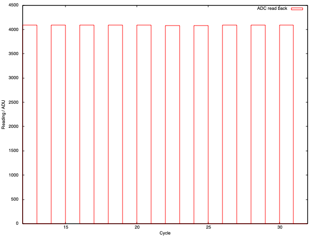
So, averaging should work fine, just be aware that this is “instant samples.”