Graeme Winter
Very basic Verilog
Start at the very bottom -> did not get on well with the clicky stuff. Simple task: implement a counter to blink some lights / drive some GPIO into a scope.
Hardware
Many parts to hardware, want to use JE output (mapped to 8-bit) and basic sysclk which in this board runs at 125 MHz (which feels … familiar). Job: take clock and step it down enought to have a four bit counter on LEDs you can actually read. Bonus points: include the switches to enable or disable LEDs.
Code
Actually starts off with the constraints for the board, which is writtel in tcl:
# system clock

set_property -dict { PACKAGE_PIN K17   IOSTANDARD LVCMOS33 } [get_ports { sysclk }];
create_clock -add -name sys_clk_pin -period 8.00 -waveform {0 4} [get_ports { sysclk }];

# switches

set_property -dict { PACKAGE_PIN G15   IOSTANDARD LVCMOS33 } [get_ports { sw[0] }];
set_property -dict { PACKAGE_PIN P15   IOSTANDARD LVCMOS33 } [get_ports { sw[1] }];
set_property -dict { PACKAGE_PIN W13   IOSTANDARD LVCMOS33 } [get_ports { sw[2] }];
set_property -dict { PACKAGE_PIN T16   IOSTANDARD LVCMOS33 } [get_ports { sw[3] }];

# LED output ports

set_property -dict { PACKAGE_PIN M14   IOSTANDARD LVCMOS33 } [get_ports { led[0] }];
set_property -dict { PACKAGE_PIN M15   IOSTANDARD LVCMOS33 } [get_ports { led[1] }];
set_property -dict { PACKAGE_PIN G14   IOSTANDARD LVCMOS33 } [get_ports { led[2] }];
set_property -dict { PACKAGE_PIN D18   IOSTANDARD LVCMOS33 } [get_ports { led[3] }];

# JE output port

set_property -dict { PACKAGE_PIN V12   IOSTANDARD LVCMOS33 } [get_ports { je[0] }];
set_property -dict { PACKAGE_PIN W16   IOSTANDARD LVCMOS33 } [get_ports { je[1] }];
set_property -dict { PACKAGE_PIN J15   IOSTANDARD LVCMOS33 } [get_ports { je[2] }];
set_property -dict { PACKAGE_PIN H15   IOSTANDARD LVCMOS33 } [get_ports { je[3] }];
set_property -dict { PACKAGE_PIN V13   IOSTANDARD LVCMOS33 } [get_ports { je[4] }];
set_property -dict { PACKAGE_PIN U17   IOSTANDARD LVCMOS33 } [get_ports { je[5] }];
set_property -dict { PACKAGE_PIN T17   IOSTANDARD LVCMOS33 } [get_ports { je[6] }];
set_property -dict { PACKAGE_PIN Y17   IOSTANDARD LVCMOS33 } [get_ports { je[7] }];
Given this the program is almost trivial:
`timescale 1ns / 1ps

// removed comment block

module blinky(
    input sysclk,
    input [3:0] sw,
    output [3:0] led,
    output [7:0] je
    );
    reg[27:0] count = 0;
    assign led = count[27:24] & sw;
    assign je = count[17:10];
    always @ (posedge(sysclk)) count <= count + 1;
endmodule
This then counts the LEDs as bits 27-24 iff the switches allow, and then 17-10 on the GPIO so you can hook up a ‘scope:
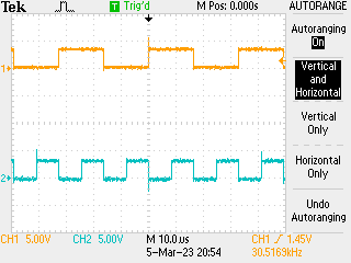
Happy there…