Graeme Winter
PIO for DAC driving
Driving a DAC with a PIO is well established technology in C: the pico signal generator does exactly this and will be revisited from µPython later. Meanwhile however the question arises of how to send the symbols for a 6-bit DAC from the PIO without messing around with DMA right now.
PIO is good for up to 5 bit numbers because of the structure of the assembly. Simply counting down from 31 is therefore a good way of driving five of the bits, and the sixth can be done by side-set e.g.
from machine import Pin
from rp2 import PIO, StateMachine, asm_pio

# use pin0 as sideset, 1...5 as "data"
pins = [Pin(j) for j in range(6)]


@asm_pio(
    sideset_init=PIO.OUT_LOW,
    out_init=(PIO.OUT_LOW, PIO.OUT_LOW, PIO.OUT_LOW, PIO.OUT_LOW, PIO.OUT_LOW),
    out_shiftdir=PIO.SHIFT_RIGHT,
)
def saw():
    wrap_target()
    set(x, 31)
    label("tick")
    mov(osr, x)
    out(pins, 5).side(1)
    nop()
    nop().side(0)
    jmp(x_dec, "tick")
    wrap()


sm = StateMachine(0, saw, freq=12500, sideset_base=pins[0], out_base=pins[1])
sm.active(1)
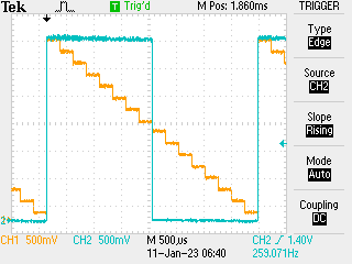
This is fine but the timing needs some work, as each of the symbols from 0b111111 to 0b000000 are visited but not for the same amount of time. Running with just four bits (so 16 symbols) with
from machine import Pin
from rp2 import PIO, StateMachine, asm_pio

# use pin0 as sideset, 1...5 as "data"
pins = [Pin(j) for j in range(6)]
for p in pins:
    p.off()


@asm_pio(
    sideset_init=PIO.OUT_LOW,
    out_init=(PIO.OUT_LOW, PIO.OUT_LOW, PIO.OUT_LOW),
    out_shiftdir=PIO.SHIFT_RIGHT,
)
def saw():
    wrap_target()
    set(x, 31)
    label("tick")
    mov(osr, x)
    out(pins, 5).side(1)
    nop()[1]
    nop().side(0)
    jmp(x_dec, "tick")
    wrap()


sm = StateMachine(0, saw, freq=12500, sideset_base=pins[2], out_base=pins[3])
sm.active(1)
Showed where the extra no-op was needed to balance the counting… at least it appears to be so: the scope did seem to show some timing jitter which is odd…

To do this better will involve using a second PIO program to read from the pins and send the symbols back out to main memory for manual inspection -> DMA time… done. With a little revision and some careful debugging have a second state machine triggered at the same instant counting back - which works fine but is somewhat limited as the set x 31 command it opens with causes an extra zero-count…
from machine import Pin, mem32
from rp2 import PIO, StateMachine, asm_pio
from uctypes import addressof

# state maachine allocation (both on PIO0)
# machine 0 -> signal generator
# machine 1 -> signal reader

# useful DREQ definition
DREQ_PIO0_RX1 = 5

# register definitions
PIO0_BASE = 0x50200000
PIO0_CTRL = PIO0_BASE + 0x0
PIO0_FSTAT = PIO0_BASE + 0x4
PIO0_RXF1 = PIO0_BASE + 0x24

# DMA registers
DMA_BASE = 0x50000000
CH0_READ_ADDR = DMA_BASE + 0x0
CH0_WRITE_ADDR = DMA_BASE + 0x4
CH0_TRANS_COUNT = DMA_BASE + 0x8
CH0_CTRL_TRIG = DMA_BASE + 0xC

# use pin0 as sideset, 1...5 as "data"
pins = [Pin(j) for j in range(6)]


@asm_pio(
    sideset_init=PIO.OUT_LOW,
    out_init=(PIO.OUT_LOW, PIO.OUT_LOW, PIO.OUT_LOW, PIO.OUT_LOW, PIO.OUT_LOW),
    out_shiftdir=PIO.SHIFT_RIGHT,
)
def saw():
    wrap_target()
    set(x, 31)
    label("tick")
    mov(osr, x)
    out(pins, 5).side(1)
    nop()
    nop().side(0)
    jmp(x_dec, "tick")
    wrap()


# auto-push / push on 32 bits to FIFO / join FIFOs
@asm_pio(
    autopush=True, push_thresh=32, in_shiftdir=PIO.SHIFT_RIGHT, fifo_join=PIO.JOIN_RX
)
def eight_bits_in():
    wrap_target()
    in_(pins, 8)
    wrap()


# set up scratch array to copy results to
COUNT = 256
scratch = bytearray(COUNT)

# set up DMA from PIO ISR
QUIET = 0x1 << 21
DREQ = DREQ_PIO0_RX1 << 15
WRITE_INCR = 0x1 << 5
DATA_SIZE = 0x2 << 2
ENABLE = 0x1

# clear FIFO
while not (mem32[PIO0_FSTAT] & (1 << 9)):
    _ = mem32[PIO0_RXF1]

mem32[CH0_READ_ADDR] = PIO0_RXF1
mem32[CH0_WRITE_ADDR] = addressof(scratch)
mem32[CH0_TRANS_COUNT] = COUNT // 4
mem32[CH0_CTRL_TRIG] = QUIET + DREQ + WRITE_INCR + DATA_SIZE + ENABLE

# trigger DMA on DREQ from PIO (1 word depth trigger)
# read bytes for as long as needed (should be multiple of 4)
tick = StateMachine(0, saw, freq=12500, sideset_base=pins[0], out_base=pins[1])

# this is reading eight pins not 6 bit I think that doesn't matter as all pins
# are wired for input
bits = StateMachine(1, eight_bits_in, freq=12500, in_base=pins[0])

# FIXME I should probably reset the clocks here

# activate
mem32[PIO0_CTRL] = 0x3

# wait for DMA completion
BUSY = 0x1 << 24

while mem32[CH0_CTRL_TRIG] & BUSY:
    continue

# stop
mem32[PIO0_CTRL] = 0

for j in range(COUNT):
    print(scratch[j])
Nice example though: should set a second DMA feeding bytes in so we can completely go around the loop. More interesting would be go hook up a second pico to the first with a clock on a side-set so we can see how fast we can read across 8 x 150mm jumpers. All symbols were in the output 3 times except for zero which was there for four.