Graeme Winter
Probing the PWM
From a couple of days ago there was code which drives the PWM carefully to output a 6 bit sawtooth: now hook this up to the PIO input from yesterday to start probing how reliable this appears to be. The key is writing out the PWM at a well defined speed, with all clocks reset before the start, then reading back the symbols over DMA which should allow a reasonable speed. N.B. the PWM has a minimum count time of 0.8µs with the code below as there are 100 clock ticks / cycle, so the PIO needs to be read at a frequency no less than 2.5MHz to capture the 50% duty cycle of the PWM.
# use the PWM to generate a 6-bit symbol counter from
# 0x3f...0 then measure it in real time with 8 bit PIO
# reader / DMA

from machine import Pin, mem32
from rp2 import PIO, StateMachine, asm_pio
from uctypes import addressof

# set up PWM function on GPIO, 2, 4, 6, 8, 10 because
# each is wired to a unique PWM
IO_BANK_BASE = 0x40014000
for j in 0, 2, 4, 6, 8, 10:
    GPIO_CTRL = IO_BANK_BASE + j * 0x8 + 0x4
    mem32[GPIO_CTRL] = 0x4

# activate PWM
PWM_TOP = 0x40050000
CH_CSR = PWM_TOP + 0x0
CH_DIV = PWM_TOP + 0x4
CH_CTR = PWM_TOP + 0x8
CH_CC = PWM_TOP + 0xC
CH_TOP = PWM_TOP + 0x10
CH_WIDTH = 0x14

PWM_EN = PWM_TOP + 0xA0

for j in 0, 1, 2, 3, 4, 5:
    TOP = 100 * 2**j - 1
    CC = 50 * 2**j - 1
    X = CH_WIDTH * j
    mem32[CH_CSR + X] = 0x0
    mem32[CH_DIV + X] = 1 << 4
    mem32[CH_CTR + X] = 0
    mem32[CH_TOP + X] = TOP
    mem32[CH_CC + X] = CC

# enable PWM 0....5
mem32[PWM_EN] = 0x3F

# useful DREQ definition
DREQ_PIO0_RX1 = 5

# register definitions
PIO0_BASE = 0x50200000
PIO0_CTRL = PIO0_BASE + 0x0
PIO0_FSTAT = PIO0_BASE + 0x4
PIO0_RXF1 = PIO0_BASE + 0x24

# DMA registers
DMA_BASE = 0x50000000
CH0_READ_ADDR = DMA_BASE + 0x0
CH0_WRITE_ADDR = DMA_BASE + 0x4
CH0_TRANS_COUNT = DMA_BASE + 0x8
CH0_CTRL_TRIG = DMA_BASE + 0xC

# use pin0 as sideset, 1...5 as "data"
pins = [Pin(j + 16) for j in range(8)]

# auto-push / push on 32 bits to FIFO / join FIFOs
@asm_pio(
    autopush=True, push_thresh=32, in_shiftdir=PIO.SHIFT_RIGHT, fifo_join=PIO.JOIN_RX
)
def eight_bits_in():
    wrap_target()
    in_(pins, 8)
    wrap()


# set up scratch array to copy results to
COUNT = 1024
scratch = bytearray(COUNT)

# set up DMA from PIO ISR
QUIET = 0x1 << 21
DREQ = DREQ_PIO0_RX1 << 15
WRITE_INCR = 0x1 << 5
DATA_SIZE = 0x2 << 2
ENABLE = 0x1

# clear FIFO
while not (mem32[PIO0_FSTAT] & (1 << 9)):
    _ = mem32[PIO0_RXF1]

mem32[CH0_READ_ADDR] = PIO0_RXF1
mem32[CH0_WRITE_ADDR] = addressof(scratch)
mem32[CH0_TRANS_COUNT] = COUNT // 4
mem32[CH0_CTRL_TRIG] = QUIET + DREQ + WRITE_INCR + DATA_SIZE + ENABLE

# this is reading eight pins not 6 bit I think that doesn't matter as all pins
# are wired for input
bits = StateMachine(1, eight_bits_in, freq=2500000, in_base=pins[0])

# activate
mem32[PIO0_CTRL] = 0x2

# wait for DMA completion
BUSY = 0x1 << 24

while mem32[CH0_CTRL_TRIG] & BUSY:
    continue

# stop
mem32[PIO0_CTRL] = 0x0
mem32[PWM_EN] = 0x0

# verify that all symbols were shown an equal number of times

counts = {}
for j in range(COUNT):
    if not scratch[j] in counts:
        counts[scratch[j]] = 0
    counts[scratch[j]] += 1

for j in sorted(counts):
    print(j, counts[j])
Code will print the list of symbols which have been captured and the number of times they were observed: shows that the capture works reasonably. Can use similar code to e.g. show that each state is in place for 400ns and also to look for the transitions to work out quite how synchronised the fastest changing bits are (surprise: when you run at full clock speed of the ‘2040 you start seeing shearing…)
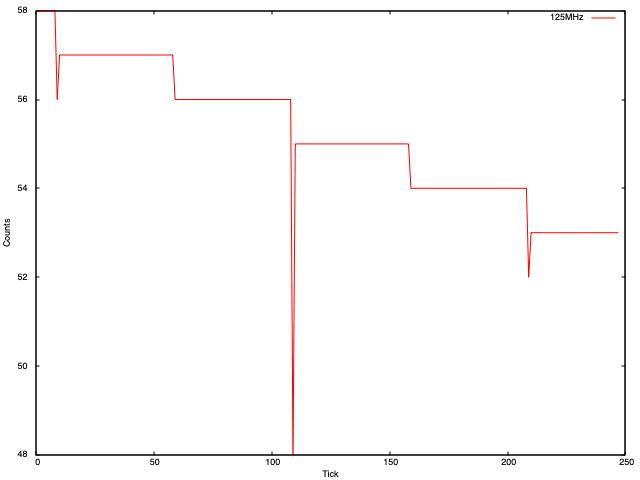
This is only on the transition points and is not really a surprise as the pins have to change from high to low or vice versa at some point in the cycle… but it is a caveat usus since there are some limits. Update: after some thought it occurred to me that the in and out GPIOs are connected by standard Dupont jump wires so probably at an 8ns clock we have a non-zero quantity of capacitance.